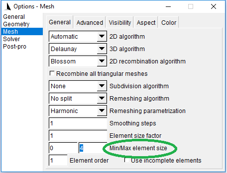
Several field, use the Min or Max field (see below). Only one background field can be given if you want to combine Select the expression-th field as the one used to compute element Set the option string of the expression-th field. string = char-expression | expression | expression-list The newĬreate a new field (with id number expression), of typeįield. Identification numbers are listed in expression-list. Modify the prescribed mesh element size of the points whose Here are the mesh commands that are related to the specification ofĬharacteristic Length = expression Mesh.CharacteristicLengthMin, Mesh.CharacteristicLengthMaxĪnd Mesh.CharacteristicLengthFactor options (see section Mesh options list) The three aforementioned methods can be used simultaneously, in whichĬase the smallest element size is selected at any given point.Īll element sizes are further constrained by the The list of available fields with their options is given below. Geometry points and lines specified by an Attractor field.Ī MathEval field specifies the size of the mesh using an explicitĪ Min field specifies the size as the minimum of the sizesįields are supported by all the algorithms except those based on The GUI by selecting ‘Apply as background mesh’ in the post-processingĪ Box field specifies the size of the elements inside and outsideĪ Threshold field specifies the size of the mesh according to theĭistance to some geometrical entities. Line using the -bgm option (see section Command-line options), or in (Note that you can also load a background mesh directly from the command Used, since the mesh used to define the field will be destroyed during pos’) filesĬan currently be used as background meshes (‘. Mesh (usually through an error estimation procedure, in an iterative

This method is very general but it requires aįirst (usually rough) mesh and a way to compute the target sizes on this Various fieldsĪ PostView field specifies an explicit background mesh in theįorm of a scalar post-processing view (see Post-processing commands, and File formats) in which the nodal values are the Not by default), the mesh will be adapted with respect to the curvatureįinally, you can specify general mesh size “fields”. Second, if Mesh.CharacteristicLengthFromCurvature is set (it is Transfinite and extruded grids: see Structured grids). The final element sizes are of course constrained by the structuredĪlgorithms for which the element sizes are explicitly specified (e.g., This method works with all the algorithms implemented in the mesh In order to get the desired element sizes. So that you may have to add “dummy” geometrical entities in the model This might sometimes lead to over-refinement in some areas, Linearly interpolating these values on the initial mesh (see The size of the mesh elements will then be computed by Geometrical points of the model (with the Point command: see Test 3 from ex10 constrains the headwater cells (with marker 1) to have volume less than 0.01, and the river channel cells (with marker 2) to be smaller than 0.There are three ways to specify the size of the mesh elements for aįirst, if Mesh.CharacteristicLengthFromPoints is set (it is byĭefault), you can simply specify desired mesh element sizes at the

Static PetscErrorCode CreateDomainLabel ( DM dm ) We can regularly refine the surface before extrusion using -dm_refine, where k is the number of refinements,

We will focus on the first type of adaptivity in this tutorial. Adaptive refinement can be controlled using tagging of cells, as well as specifying a target metric for the refined mesh. In PETSc, we can refine meshes uniformly and adaptively. Similarly, there are 9 2-cells, but 5 of them stretch between the two surfaces, meaning they are tensor products of two segments. We can see this another way in the celltype label, where there are ten mesh points of type 1, meaning segments, and four mesh points of type 2, meaning tensor products of a vertex and segment. This is exactly what we see, since there are 14 1-cells, but 4 of them noted in parentheses are tensor cells created by extrusion. The original surface mesh had 5 edges, so we would expect 10 edges for the two surfaces and four edges connecting those surfaces. We can see that there are two 3-cells, meaning three-dimensional cells, and from the celltype label we see that those cells have celltype 9, meaning they are triangular prisms. DM Object : Mesh 1 MPI process type : plex Mesh in 3 dimensions : Number of 0 - cells per rank : 8 Number of 1 - cells per rank : 14 ( 4 ) Number of 2 - cells per rank : 9 ( 5 ) Number of 3 - cells per rank : 2 Labels : celltype : 6 strata with value / size ( 3 ( 4 ), 9 ( 2 ), 0 ( 8 ), 2 ( 4 ), 1 ( 10 ), 5 ( 5 )) depth : 4 strata with value / size ( 0 ( 8 ), 1 ( 14 ), 2 ( 9 ), 3 ( 2 )) marker : 1 strata with value / size ( 1 ( 24 )) Face Sets : 1 strata with value / size ( 1 ( 12 ))


 0 kommentar(er)
